
Your sonar setup has more than one position. The cable route that looks clean while the boat is parked may behave differently when a mount rotates or equipment is stowed. Before changing settings to chase an intermittent problem, take a careful look at the physical setup.
A practical clearance check
Use your equipment's documented inspection procedure, secure the boat, and keep hands clear of moving mechanisms. Do not energize a propeller for this check. This is an observation routine, not a replacement installation specification.
- Start at rest. Photograph the cable path, connector area and mounting points. Look for an already flattened jacket, abrasion, a sharp bend or a connector carrying tension.
- Observe each permitted position. Following the mount's instructions, inspect stowed, deployed and normal steering positions. Watch where the cable crosses joints and edges. Stop if motion pulls the cable tight or traps it.
- Check the return journey. A loop that clears deployment can fall into a pinch point on the way back. Observe both directions without putting fingers into the mechanism.
- Document the exact problem. Record the position and contact point. Compare the routing with the correct installation manual before moving clamps, adding an extension or changing attachment points.
One manufacturer example, with a specific scope
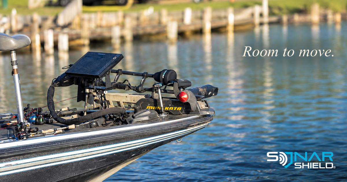
Garmin's July 2026 LiveScope 2 instructions for the bottom Spy Pole mount call for securing the transducer cable, avoiding nearby electrical interference sources and routing it clear of pinch points during deployment and stowage. Cable damage can cause transducer failure. Those instructions apply to that installation; the photo here is illustrative and does not identify a Spy Pole setup. Read Garmin's installation instructions.
Why there is no universal slack measurement here
The needed movement, cable type and approved mounting hardware vary. More loose cable is not automatically a solution: it can create another snag. We do not recommend a universal loop size, bend radius or tie spacing without the applicable manufacturer's specification. If the manual does not resolve your concern, send the manufacturer or installer your model names and photos of the problem position.
A cover protects only what it is designed to cover. It does not replace correct cable routing or an installation check. For help documenting an issue, use our fish finder troubleshooting checklist.
Community question: Which position revealed a clearance problem in your setup: stow, deploy or steering? Describe the observation and your equipment model so others can learn from it.